Building a 'Quieter-than-a-Whisper' Mini-PC |
Index |
WARNING! This project involves some soldering and in the worst case of error your motherboard and devices attached to it can be permanently damaged. Do not follow my advises unless you know what you are doing.
It is quite unexpected that the USB ports on the back panel work in the USB mode 1.1 only in spite of the motherboard and chipset specifications. I do not mind having several of them for such applications like printer, mouse, infrared devices, etc., which do not need faster interface anyway. But it would be nice to have also some 2.0 USB ports on the back for a permanently attached scanner and an external storage device. The USB port installed on the motherboard supports USB 2.0 mode and takes up to 4 nodes. Two of them are attached to the front panel USB connectors. To use the other two I installed a USB bracket on the back panel. However, the problem is that the on-board USB connector has 16 pins and does not allow connecting it to two standard 10-pin USB plastic connectors. I do not have a 16-pin USB connector, so I combined it from two standard 10-pin ones by reassigning the conductors within the connector.
To disassemble the conductors one should use a small screwdriver and carefully lift up the plastic lock as it is shown on the next picture. This releases the conductor and it then can be pulled out of the connector.
The modified USB bracket conductors layout should be as shown in the picture below. Pay a particular attention to the conductors color. Only 3 pins out of 5 are used on each side of the conductor, the red ends remain hanging for now, see more on that below.
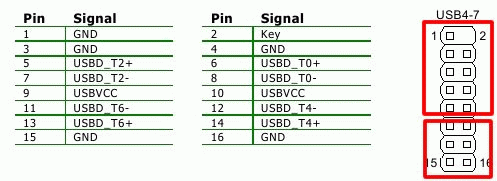
The pin layout of the on-board 16-pin USB connector is shown on the next image. The red rectangles are the 10-pin USB external connectors. The top one is the original one that came with the case, the bottom one is the modified one from the bracket. The problem to use two connectors is that the USBVCC is covered by the top one, so that the bottom one cannot power up the USB devices attached to it in a simple setting. This is OK if used with devices that do not need any power from the motherboard, e.g. scanner, or external storage based on a 3.5" HDD that usually has a separate power supply anyway. If it is desirable that the USB connector on the back of the case provides power to external devices, the hanging red ends above must be connected to pins 9 and 10 of the on-board connector. Just solder them to the corresponding red conductors of the top connector. That is what I did and it works fine. A safer solution would be to connect the red wires to +12V somewhere on the power converter board to prevent overloading of the USB power bus.

To make sure, here is the pinout of the USB connector. Use this info to assemble the conductors for the bottom connector.
 |
|